
Instruction
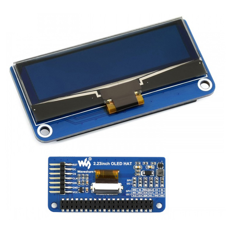
Il s’agit d’un écran OLED de 2,23 pouces avec un contrôleur. Vous pouvez l’ajouter directement sur Raspberry Pi par l’en-tête 40 PIN, ou le connecter à une autre plateforme matérielle via les interfaces IIC et SPI. L’interface du HAT OLED 2,23 pouces est le SPI par défaut, vous pouvez également passer à I2C en soudant les résistances à l’arrière de l’OLED.
spécification
- Contrôleur : SSD1305
- Interface : SPI/I2C/OLED
- Résolution: 128*32
- Taille de l’écran : 2,23 pouces
- Taille des pixels : 0,41 mm x 0,39 mm
- Couleur d’affichage: Blanc
- Tension de fonctionnement : 3,3 V
- Température de fonctionnement : -40 ~ 70 ℃
ÉPINGLE

| ÉPINGLE | Description |
|---|---|
| VCC | 3,3 V/5 V |
| GND | GND |
| DEPUIS | Entrée de données |
| CLK | Entrée horloge |
| CS | Sélection de puce (faible actif) |
| CC | registre / Sélection des données (SPI) |
| TVD | Réinitialisation (faible actif) |
Le module utilise le mode de communication SPI par défaut, c’est-à-dire que BS1, BS2, DIN, CLK, CS et DS connectent la résistance 0R aux deux plots supérieurs par défaut. La méthode de soudage illustrée dans la figure ci-dessus consiste à sélectionner la méthode de communication I2C. La connexion matérielle spécifique est indiquée dans le tableau suivant : Remarque : L’image ci-dessus représente la soudure sur le matériel, le tableau suivant représente la connexion matérielle réelle.
| Communication | BS1 | BS2 | DEPUIS | CLK | CS | CC |
|---|---|---|---|---|---|---|
| IPS | GND | NC | FUMÉE | SCLK | CS | CC |
| 12C | 3V3 | DEPUIS | SDA | SCL | GND | GND |
Principe de fonctionnement
- Le SSD1305 est un contrôleur OLED de 132*64 pixels, mais l’OLED n’a que 128*32 pixels, donc l’écran n’utilise que la première partie du cache SSD1305 ;
- L’OLED prend en charge le parallèle 8 bits 8080, SPI et I2C, ainsi que d’autres méthodes de communication, mais compte tenu de la taille du module et de l’économie des précieuses ressources IO du microcontrôleur, la méthode parallèle 8 bits 8080 est abandonnée et prend en charge la méthode de communication I2C et SPI.
Protocole de communication I2C

- Pendant la communication I2C, envoyez d’abord une adresse de périphérique esclave de 7 bits + 1 bit de lecture et d’écriture, et attendez la réponse de l’appareil.
- Une fois que le périphérique esclave a répondu, un octet de contrôle est envoyé, qui détermine si l’octet suivant est une commande ou des données, puis attend que le périphérique esclave réponde.
- Une fois que le périphérique esclave a répondu à nouveau si une commande est envoyée, seule une commande d’un octet est envoyée. Si des données sont envoyées, un seul octet peut être envoyé, ou plusieurs octets de données peuvent être envoyés ensemble, selon la situation.
- Voir la fiche technique page 22, figure 8-6 pour plus de détails.
Calendrier de communication SPI

- Comme le montre la figure ci-dessus, les données sur SDIN sont décalées dans un registre à décalage de 8 bits à chaque front montant de SCLK dans le premier ordre MSB LSB.
- D/C# est échantillonné toutes les 8 horloges et les données du registre à décalage sont écrites dans la mémoire d’affichage graphique (GDDRAM) ou dans le registre de commandes, à la même horloge de comptage.
- En mode série, seules les opérations d’écriture sont autorisées. Processus d’opération d’écriture en mode 4-wireSPI.
- Voir la figure 8-5 sur la fiche technique page 21 pour plus de détails.
Tarte aux framboises
Fournit une démo C et Python
- Ouvrez le terminal Raspberry Pi et entrez la commande suivante pour accéder à l’interface de configuration
Avis
Il n’y a pas encore d’avis.